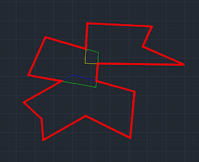
This picture shows 3 polygons overlapping each other:
This picture shows the outline (in red) we want to obtain:
In this article, to simplify the code and the discussion, let me limit the entities are all closed Polylines, and each Polyline overlaps with at least 1 other Polyline (so that a continuous outline can be formed); also I only care to get an exterior outline and ignore possible islands inside the outline. Obviously, I should expect to obtain a Polyline, as the red outline shown in picture above, or a series of points that are the vertices of the Polyline.
How to proceed with .NET API code to do this? After some tries, I settled with these 2 steps:
1. Converting each Polyline to Region, then use Region.BooleanOperation() method to merge/unite all the closed Polylines into one single Region;
2. Use Brep API to generate a BrepEntity from the Region, then find the exterior loop of the BrepEntity. These exterior loop provides all the vertices of outline Polyline.
Here is the code that implements the thought of the process:
using System.Collections.Generic;
using System.Linq;
using Autodesk.AutoCAD.ApplicationServices;
using Autodesk.AutoCAD.DatabaseServices;
using Autodesk.AutoCAD.Geometry;
using CadDb = Autodesk.AutoCAD.DatabaseServices;

using Autodesk.AutoCAD.BoundaryRepresentation;

namespace GetOutLine
{
    public class OutLiner
    {
        private Document _dwg;

        public OutLiner(Document dwg)
        {
            _dwg = dwg;
        }

        public void DrawOutline(IEnumerable<ObjectId> entIds)
        {
            using (var polyline = GetOutline(entIds))
            {
                using (var tran = _dwg.TransactionManager.StartTransaction())
                {
                    var space = (BlockTableRecord)tran.GetObject(
                        _dwg.Database.CurrentSpaceId, OpenMode.ForWrite);
                    space.AppendEntity(polyline as Entity);
                    tran.AddNewlyCreatedDBObject(polyline as Entity, true);
                    tran.Commit();
                }
            }
        }

        public Entity GetOutline(IEnumerable<ObjectId> entIds)
        {
            var regions = new List<Region>();

            using (var tran = _dwg.TransactionManager.StartTransaction())
            {
                foreach (var entId in entIds)
                {
                    var poly = tran.GetObject(entId, OpenMode.ForRead) as Polyline;
                    if (poly!=null)
                    {
                        var rgs = GetRegionFromPolyline(poly);
                        regions.AddRange(rgs);
                    }

                }

                tran.Commit();
            }

            using (var region = MergeRegions(regions))
            {
                if (region != null)
                {
                    var brep = new Brep(region);
                    var points = new List<Point2d>();
                    var faceCount = brep.Faces.Count();
                    var face = brep.Faces.First();
                    foreach (var loop in face.Loops)
                    {
                        if (loop.LoopType == LoopType.LoopExterior)
                        {
                            foreach (var vertex in loop.Vertices)
                            {
                                points.Add(new Point2d(vertex.Point.X, vertex.Point.Y));
                            }
                            break;
                        }
                    }

                    return CreatePolyline(points);
                }
                else
                {
                    return null;
                }
            }
        }

        #region private methods

        private List<Region> GetRegionFromPolyline(CadDb.Polyline poly)
        {
            var regions = new List<Region>();

            var sourceCol = new DBObjectCollection();
            var dbObj = poly.Clone() as CadDb.Polyline;
            dbObj.Closed = true;
            sourceCol.Add(dbObj);

            var dbObjs = Region.CreateFromCurves(sourceCol);
            foreach (var obj in dbObjs)
            {
                if (obj is Region) regions.Add(obj as Region);
            }

            return regions;
        }

        private Region MergeRegions(List<Region> regions)
        {
            if (regions.Count == 0) return null;
            if (regions.Count == 1) return regions[0];

            var region = regions[0];
            for (int i=1; i<regions.Count; i++)
            {
                var rg = regions[i];
                region.BooleanOperation(BooleanOperationType.BoolUnite, rg);
                rg.Dispose();
            }

            return region;
        }

        private CadDb.Polyline CreatePolyline(List<Point2d> points)
        {
            var poly = new CadDb.Polyline(points.Count());

            for (int i=0; i<points.Count;i++)
            {
                poly.AddVertexAt(i, points[i], 0.0, 0.3, 0.3);
            }

            poly.SetDatabaseDefaults(_dwg.Database);
            poly.ColorIndex = 1;

            poly.Closed = true;

            return poly;
        }

        #endregion
    }
}
Here is the command that makes above code in action:
using Autodesk.AutoCAD.DatabaseServices;
using Autodesk.AutoCAD.EditorInput;
using Autodesk.AutoCAD.Runtime;
using CadApp = Autodesk.AutoCAD.ApplicationServices.Application;

[assembly: CommandClass(typeof(GetOutLine.Commands))]

namespace GetOutLine
{
    public class Commands
    {
        [CommandMethod("Outline")]
        public static void RunMyCommand()
        {
            var dwg = CadApp.DocumentManager.MdiActiveDocument;
            var ed = dwg.Editor;

            try
            {
                var ids = SelectPolylines(ed);
                if (ids != null)
                {
                    var liner = new OutLiner(dwg);
                    liner.DrawOutline(ids);
                }
                else
                {
                    ed.WriteMessage("\n*Cancel*");
                }
            }
            catch (System.Exception ex)
            {
                ed.WriteMessage("\nCommand failed:\n{0}", ex.Message);
                ed.WriteMessage("\n*Cancel*");
            }
        }

        private static ObjectId[] SelectPolylines(Editor ed)
        {
            var vals = new TypedValue[]
            {
                new TypedValue((int)DxfCode.Start, "LWPOLYLINE")
            };

            var res = ed.GetSelection(new SelectionFilter(vals));
            if (res.Status == PromptStatus.OK)
                return res.Value.GetObjectIds();
            else
                return null;
        }
    }
}
Watch these video clip as the proof of how the code works.
Extra Thought
Obviously, creating a BrepEntity based on Region garantees a exterior loop/boundary will be generated, thus the outline curve. I could extend the Region generating process beyond Polyline entity or closed Curve (Circle,..). For example, if the entity is an Arc, I can draw a Line from the Arc's start point to its end point, then use these 2 entities to generate a Region; for DBText or MText, I can use its bounding box as a Polyline to generate the Region. But things could become very complicated if the overlapped entities could be any possible type of entities.Oh, beside the usual 3 AutoCAD .NET API assemblies, the project needs to set reference to BREP API assembly (acdbmgdbrep.dll).

